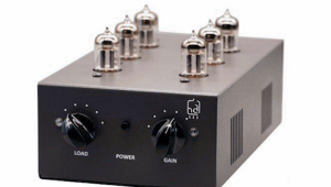
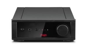
Sutherland PhD MC phono preamplifier Measurements
The PhD's plug-in modules made it very easy to perform complete sets of measurements in all its various modes. I used an almost fresh set of batteries to power it.
The voltage gain at 1kHz accurately conformed to the specified figures. I measured 45.6dB ("45"), 49.7dB ("50"), 55.05dB ("55"), and 61.1dB ("60"). The input impedance (at 1kHz) also accurately tracked the specification: 99.8 ohms ("100"), 199.4 ohms ("200"), 973.9 ohms ("1k"), and 43k ohms ("47k"). The PhD's output impedance was usefully low, at 251 ohms across the audioband. However, there was a significant DC offset present on the outputs (–17.5mV on the left channel, +8.7mV on the right) that might give rise to pops when switching the partnering preamp's inputs.
The RIAA error was extremely low on the left channel (fig.1, solid trace), but the right channel had a +0.3dB rise through the treble octaves (dashed trace). Channel separation was a good 70dB in the treble, but worsened to a still acceptable 60dB at low frequencies (not shown). The signal/noise ratio depended on the voltage gain selected, but even at the maximum 60dB setting, the A-weighted figure (ref. 500µV at 1kHz) was a good 59dB. Reducing the gain to 45dB increased this figure to an excellent 91.2dB, ref. a 5mV input voltage. As expected, however, the unweighted wideband ratios were worse, at 29dB and 63dB for "60" and "45" settings, respectively.

Fig.1 Sutherland PhD, RIAA error (right channel dashed, 0.5dB/vertical div.).
Even at a high 10mV input at 1kHz, the measured THD+noise percentage remained below the noise floor in the audioband, though the waveform starts to triangulate above 30kHz, presumably due to slew-rate limiting. Looking at the spectrum of the PhD's output while driving a 1kHz tone at 1V into 4k ohms and set to 45dB gain, the THD percentage (true sum of the harmonics) was a very low 0.0086% (fig.2). The only distortion spuriae that can be seen poking their heads above the noise floor in this graph are the second, third, and fourth, at –84.7dB, –86dB, and –88.2dB, respectively. Intermodulation distortion (fig.3) was also very low, the 1kHz difference product resulting from an equal mix of 19kHz and 20kHz tones lying at –75.5dB (0.017%). (Note that the sloping noise floor in these two graphs is due to the PhD's RIAA equalization.)

Fig.2 Sutherland PhD, spectrum of 1kHz sinewave, DC–1kHz, at 1V into 4k ohms (linear frequency scale).

Fig.3 Sutherland PhD, HF intermodulation spectrum, DC–25kHz, 19+20kHz at 1V into 4k ohms (linear frequency scale).
The PhD was set to 45dB gain for these two distortion measurements. In general, the preamplifier's overload margin decreased linearly with increasing gain. So while the PhD overloaded at a high +19.1dB referenced to the standard moving-magnet output of 5mV at 1kHz when set to 45dB, this figure decreased by 5dB for each 5dB increase in gain. However, as the higher gain settings will be used with low-output moving-coil cartridges, the apparently smaller overload margin will not be a problem. Referenced to the MC standard output of 500µV, the PhD's overload margin when set to 60dB gain was a still good 18.7dB. The margins at 20Hz were as good as or slightly better than those at 1kHz. However, the 20kHz margin was around 10dB less good at all gain settings, due not to clipping as such but to the waveform triangulation I noted earlier.
The versatile Sutherland PhD offers good measured performance, but in general the user should set its gain to the lowest level that will be compatible with the cartridge output; the need to keep the noise floor below audibility; and the amount of gain applied by the system preamplifier.—John Atkinson
- Log in or register to post comments
