That Crazy Little Thing Called "Azimuth" Part 2
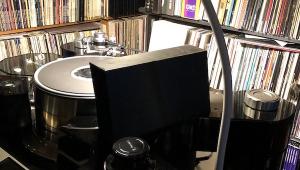
First, you need an accurate test record that includes separate left and right channel 1K (1000Hz) modulated grooves. 1K is the standard frequency used to measure crosstalk. These include Analogue Productions' The Ultimate Analogue Test Record(AAPT 1) and the Clearaudio Azimuth Optimizer Test Record. I've used the first one but have not yet tried Clearaudio's. The goal is to measure the output of both the modulated and unmodulated channels of a test record that includes separate left and right channel modulated grooves. When you play the modulated left channel test track for instance, you can measure the output as a voltage and you can also measure the channel that's not supposed to have any output since it's unmodulated. Of course this is the real world so there will be some crosstalk and some voltage generated, but it will be much lower than the modulated channel. Keep in mind that the results can only be as accurate as the test record and test records too are not perfect.
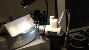
So here's the least expensive way to do this. First you will need an accurate digital voltmeter. This should cost no more than fifty dollars. Then I recommend some decent earplugs. You'll know why shortly. If you know how to build a high and low pass filters, that will make the results more accurate and easier to obtain, but don't worry, even if you don't you'll get sufficiently accurate results to make doing this very worthwhile.
(However, if you can build such filters build pairs of high pass 500Hz and low pass 2kHz filters with two sets of speaker terminals in a project box, connecting the filters to one pair that will act as the box's input. Run two pairs of short length speaker cables (in this instance lamp cord will do!) from the amp to the box's inputs and connect the voltmeter to the box's output terminals to run these tests. If you're comfortable doing so, put load resistors across the terminals and then you can run these tests with the speakers disconnected, which will obviate the need for earplugs
Whether or not you've built the box, the next step is to set the voltmeter to low AC volts (around 5 volts) and put the probes in the left channel of your amplifier's speaker terminals. Play the test record's left channel modulated band and after putting in the earplugs, turn the volume up until the voltmeter reads around 4 volts. Because of rumble and other additive distortions, the voltmeter will not remain steady at 4 volts so you'll have to 'average' it to where the meter dances back and forth evenly around 4 volts.
Now, while the modulated left channel test track is playing, move the probes to the right channel and measure the voltage. It should be very low, in the range of .15 volts. Write down the large voltage number and small voltage number.
Now, repeat the test using the right channel test track while leaving the probes in the right channel speaker terminals.Be sure you don't move the volume control on your preamp! Perhaps you'll note a slightly lower or higher reading indicating that the cartridge's output isn't identical for both channels. Write that number down and while the same test track plays move the probes to the left channel amp terminals and write down the smaller voltage.
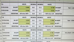
Now you have two sets of numbers. Use the chart below (which you should copy, paste and print out) generously donated to this site by Mr. Wally Malewicz, to convert the large voltage left channel and small voltage right channel to dBV and do the same for the right channel.
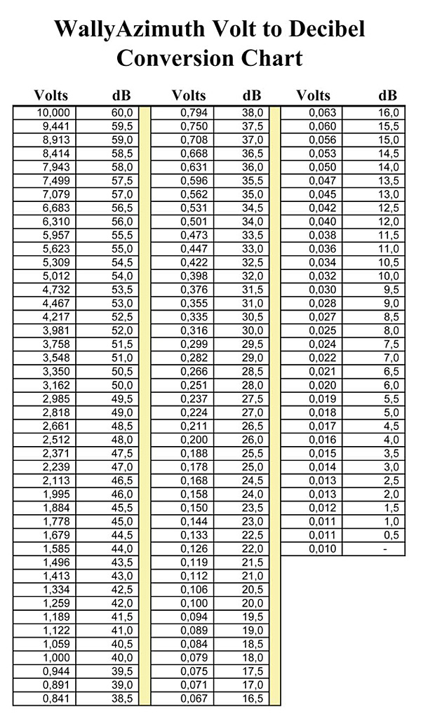
So, let's say you measured 4 volts on the left channel and then .14 on the right. The closes to 4 volts is 52dBV. The closest to .14 is 23dBV. Subtract 23 from 52 and you have 29dBV. That is the left channel separation. Now repeat using the right channel information. Chances are the final number will not be the same. If they are, you've lucked out! But don't count on it.
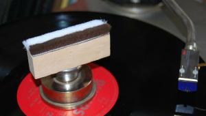
Acceptable crosstalk is around 25dBV left to right and right to left. Good is 30dBV and above that is very very good! But you are not done. If the difference between the two channels is greater than 3dBV you need to adjust azimuth setting. If you can make a tiny mark on the arm tube to serve as a reference starting point, do that.
However it's done on your arm, slightly rotate the arm tube (or headshell, etc.) in one direction (doesn't matter which) and run the test again ( I didn't say this was easy or fun!). If the new results show a worse result, you've gone in the wrong direction. So return to the original setting and then rotate further in that direction and test again.
If the first azimuth change narrowed the difference, you’re going in the correct direction. If you’re within 10 percent, you can leave it, or move it a bit more in that direction and measure again. If you’re even closer, good! If not, you’ve gone too far and will need to head back in the other direction until the two dB values are within 10% of each other. (Don't be surprised if the large voltage output changes slightly as you rotate the arm tube and make measurements).
Then you’re done. You’ve minimized and equalized as best as possible the crosstalk, thereby maximizing channel separation.
You should now hear a wider, better balanced, more symmetrical soundstage. If your initial result was sufficiently off, after correcting the azimuth you will probably be shocked by the improvement. Your jaw may drop so have a basket handy. Can we please from audio review writing phrases like "jaw dropping" and "veil lifting" (unless you are a reviewer for Taliban.com)? Please?
If you are really interested in this subject you might try running this test beginning at, say, 3 degrees to one side of perpendicularity and then every half degree or so toward perpendicularity, then perpendicularity and then to 3 degrees to the other side and then checking the results.
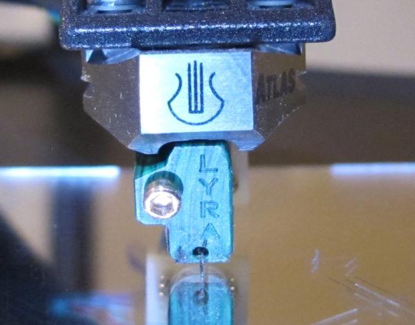
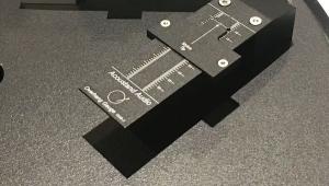
Don't be surprised or shocked to find the best result is not with the cantilever perpendicular to the record surface! However, if the result is way to one side (more than 1.5 degrees or so) and you've recently spent more than $1000 for your cartridge, I'd contact the manufacturer for a replacement (if it's new).
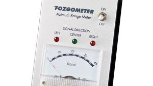
You can also use a Fozgometer ($250) to set azimuth. The procedure for using this device, invented by surround sound matrix inventor Jim Fosgate, is similar to what's just been described, but the results are relative and don't give you precise crosstalk numbers.
You can also use Dr. Feickert's Adjust + software. It costs a few hundred dollars and provides you with charts that plot the results as you rotate the arm tube. Use that link to learn more about it. You have to learn how to use the software and it's Windows only. However, the record Feickert supplies is not recommended.
Well, that's it! Please do try this at home and let us know what you hear!
P.S.: even if your tonearm doesn't allow for azimuth adjustment, run the test once to see how well your cartridge is manufactured and what kind of separation you are achieving.


| Equipment Reviews | The Gruvy Awards | Blogs Analog Tips | Columns Music | Show Reports | News Resources |
 © 2025 AnalogPlanet
AVTech Media Americas Inc.
All rights reserved